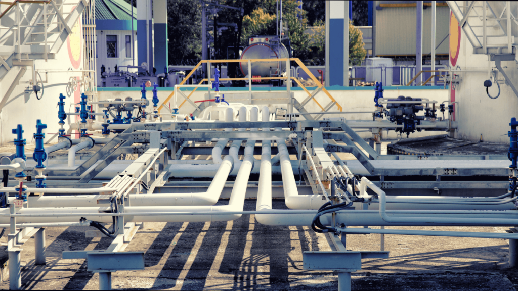
A critical consideration for ensuring a UV system's performance is the appropriate installation of upstream and downstream piping. In this article, we'll look closer at the guidelines for piping installation as per the UVDGM.
The Importance of Proper Piping Installation in UV Systems
Using ultraviolet (UV) light technology in water treatment is a widely accepted method of obtaining the safety and purity of drinking water. The United States Environmental Protection Agency (EPA) has issued the Ultraviolet Disinfection Guidance Manual (UVDGM). This provides technical information on applying UV light in public water systems. Many industrial entities, such as beverage manufacturers, aquatic facilities, and more, have adopted this manual to ensure the highest water quality standards.
However, with the growing use of UVDGM, there are questions from those unfamiliar with UV technology on the proper installation of UV systems. A critical element to consider in order to increase a UV system’s performance is the appropriate installation of upstream and downstream piping. In this article, we’ll look closer at the guidelines for piping installation as per the UVDGM.
The UVDGM has specific language on installing upstream and downstream piping to ensure the delivery of an appropriate UV dose. The guidelines recommend the following options for conformity to the UVDGM.
The UVDGM requires a minimum of 5 pipe diameters of straight pipe upstream of each UV reactor. This length should equal the size of the straight line used in the validation testing plus an additional 5 pipe diameters. For example, if 24 inches of 4-inch diameter straight pipe was used during validation, then 44 inches of a straight line (24 inches + 5 pipe diameters * 4 inches) should be installed upstream of the UV reactor.
The UVDGM requires that the inlet and outlet conditions used during validation match those used at the treatment plant for at least 10 pipe diameters upstream and 5 pipe diameters downstream of the UV reactor.
The UVDGM requires that the velocity of the water measured at evenly spaced points through a given cross-section of the flow upstream and downstream of the reactor is within 20 percent of the theoretical speed during the validation test stand and the treatment plant installation.
The most effective option for a given application depends on: the specific site layout, piping constraints, and on how the validation was obtained.
Option 1 is the most widely used solution. On the other hand, option 2 requires a pipe layout from the UV system supplier and usually requires a Non-Disclosure Agreement (NDA) to be signed.
Option 3: The UV dose delivery is determined through computational fluid dynamics (CFD) modeling of inlet and outlet conditions.

Example of pipe layout from a validation report
The Critical Role of Pipe Layout
Pipe layout before and after the UV system is critical to achieve the desired performance. Improper piping installation can result in a 25% drop in performance. This can happen even if the UV system’s display indicates that it delivers the required dose and amount of mJ/cm2 inside the chamber.

Share: